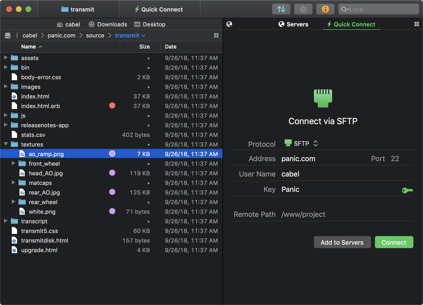
Feb 21, 2021 HBW 50 thru 250 (HBW 5 thru 20), case assemblies. HBW 50 thru 250 (HBW 5 thru 20), internal gear assemblies. HBW 150V (V-Drive), case assembly. HBW 150V (V-Drive), internal gear assembly. HBW 360 thru 630, case assembly. HBW 360 thru 630, internal gear assemblies. HBW 360A (down angle). HSW 630A (down angle), case assembly. Transmit FTP is a modern FTP application that supports a range of transfer types and services. Not only does it support FTP and SFTP, but it also allows you to transfer files to and from services like Amazon S3, or set up your own WebDAV storage. Transmit gives Mac OS X users highly usable file transfer that looks right at home in OS X.
Panasonic CR2-2PK Photo Lithium 3V Batteries for Mini 25, Mini 50, Mini 50S, Mini 55, Pivi MP-100 and SP-1- Silver (Pack of 2) 4.4 out of 5 stars 166 $8.99. Transmit 5.5.1 CR2 73.84 MB The gold standard of macOS file transfer apps just drove into the future. Transmit 5 is here. Upload, download, and manage files on tons of servers with an easy, familiar, and powerful UI. It's quite good. Transmit now connects to 10 new cloud services, like Backblaze.
TO 31R2-2GRC171-2
NAVELEX0967-LP-544-5010
current is supplied to transistor Q3 throughresistors R27
andR29.Thisforwardbiases Q3 causing it to turn on
amperes. The controlcircuitsprocess rf attenuation
(AGC)voltageandkey-linevoltage to control dc current
(about+25 V dc)developed by voltagedivideraction of
R29,R27,andthebasecircuit of Q3 reversebiases
diodeCR8.Thisenablesshuntdiodecontrolamplifier
4-227.
diode CR3 andreceiveseriesdiode CR2 respectively.
The positivevoltagedeveloped by voltagedivideraction
of R29,R27,andthebasecircuit of Q3 is alsoapplied
throughresistor R15 to thecathode of transmitseries
diodeCR1.Thisreversebiases CR1 andcauses it to
providemaximumattenuation to the rf signalbetween
thetransmitterandantennaports of thetransmit/receive
switch. Rf attenuation(AGC)voltagedeterminesthe rf
resistance of thereceiveseriesandreceiveshuntdiodes
which, in turn,determinesthe rf signalattenuation
betweenthereceiverandantennaports.
capacitorC7,andresistor R8 and to groundthrough
4-230. In receivemode, rf attenuationoccurs in stages.
U1A. The transmit-to-receiveandreceive-to-transmit
transferfunction of thetransmit/receiveswitch is
module A3 increases in a positivedirection as the rf
controlled by thecombinedcircuitaction of keyoffdelay
signalstrength at theantennaincreases.For rf signals
thatdevelop an rf attenuation(AGC)voltage of lessthan
2.5 V dc,thetransmit/receiveswitchprovidesminimum
4-228. The transferfunction of thetransmit/receive
switchoperates as follows. To switchfromreceive to
increasesabove2.5 V dc,seriesdiodecontrolamplifier
U1Bandreceiveattenuator Q4 begin to reducethe
transistor Q1 offwhich, in turn,turnstransmitenable
currentflowthroughreceiveseriesdiode CR2 to series
attenuatethereceive rf signal. At an rf attenuation
(AGC)voltage of approximately4.8 V dc, CR2 reaches
maximumsignalattenuation.Above4.8 V dc,shunt
CR1 (minimum rf resistance)andcausesthe rf signal to
be shunted to groundthroughcapacitorsC7-C2-C16and
C8.Transistor Q2 alsoshunts to groundbasedrive to
transistor Q3 causing Q3 to turnoff.Thisopensthe dc
currentpaththroughreceiveattenuator Q4 andallows a
4-231. The followingdescribescircuitaction of shunt
diodecontrolamplifierU1A,seriesdiodecontrolamplifier
resistor R14 by voltagedivideraction of resistor R28 and
R14.Thisvoltage,whenappliedthroughchoke L4 to the
(AGC)voltagevariesfrom2.5 to 8 V dc (activerange of
rf attenuation).Positive5.1-V dc powersupplyvoltage

